2 × 1
One board per speaker
Louder-ESP32-Plus: an ESP32-S3 for Wi-Fi plus a TAS5825M amplifier with a DSP. Left and right are set in software.
A Yolk hardware experiment
Designed and simulated, not yet built or measured
A pair of 3D-printed, active, two-way bookshelf speakers. Each one has its own Wi-Fi streaming amplifier with a built-in DSP crossover. You print the cabinet, screw the parts together without soldering, and stream to them from your phone or computer. This page is the build guide and the honest state of the design.
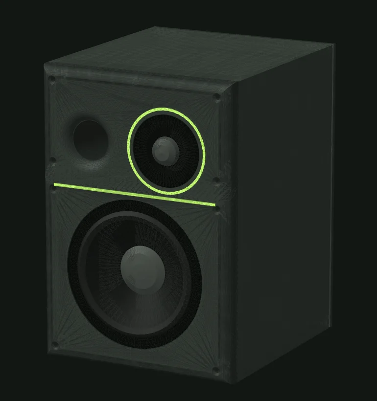
01 / What you’re building
Each speaker is a vented 5-inch-woofer-plus-dome-tweeter box. Inside the rear bay sits a small streaming amplifier board: it joins your Wi-Fi, receives the music, splits it into bass and treble with a DSP crossover, and drives the two drivers directly. There is no separate amplifier and no cable between the speakers, only a power brick for each. A subwoofer can join later over the same network.
Louder-ESP32-Plus: an ESP32-S3 for Wi-Fi plus a TAS5825M amplifier with a DSP. Left and right are set in software.
Two body halves, two baffles, port tube, two rear plates and two neon inlays, printed without supports.
Screw terminals, crimped spade terminals and lever connectors. A soldering iron is used only to press in threaded inserts.
| Item | Value |
|---|---|
| Type | 2-way vented bookshelf, one amp board per speaker |
| Drivers | SB13PFCR25-4 5" woofer + SB26STCN-C000-4 26 mm tweeter, 4 Ω |
| Net volume | 7.9 L, vent tuned to 57.5 Hz (Ø40 mm port, 114 mm)simulated |
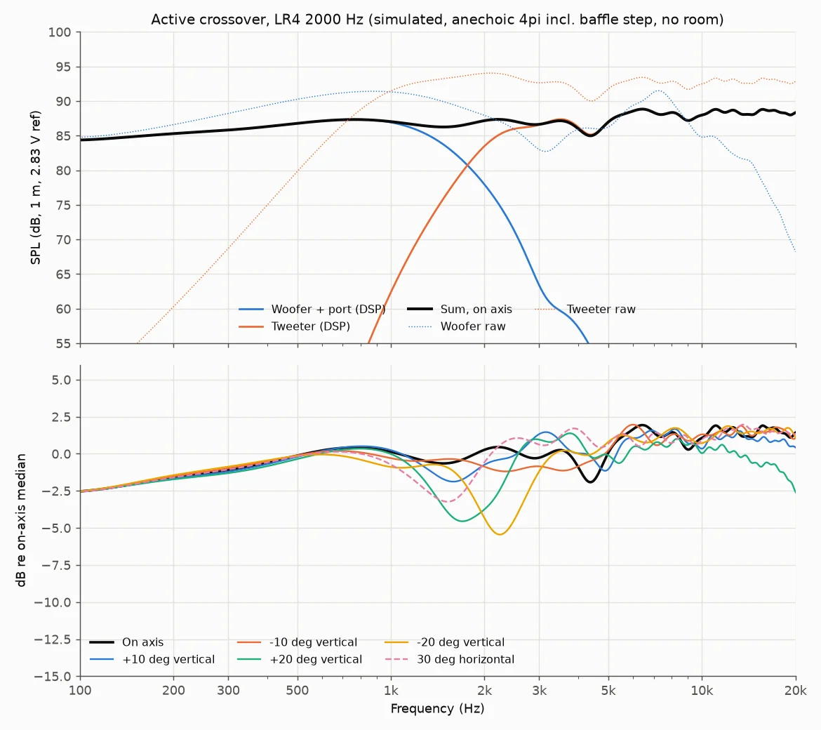
| Crossover | Linkwitz-Riley 4th order at 2.0 kHz, in the amp’s DSP |
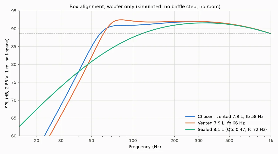
| Low end, one speaker | −3 dB at 67 Hz, −6 dB at 55 Hz (anechoic); about 49 / 45 Hz near a wallsimulated |
| Sensitivity | 86.8 dB at 2.83 V, 1 m, after a 4 dB baffle-step cutsimulated |
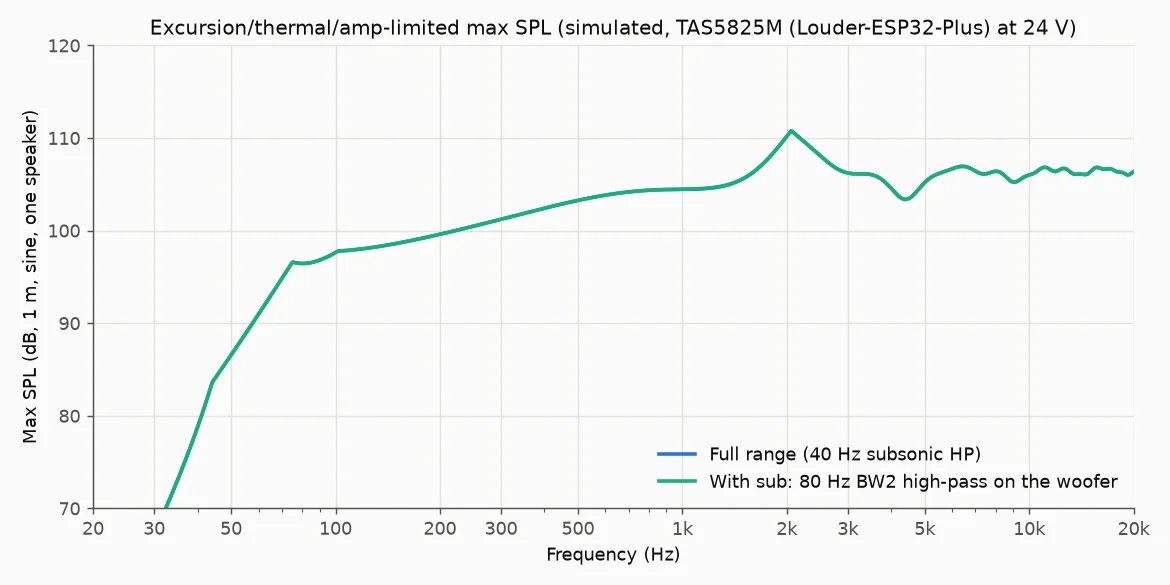
| Max level | about 96 dB at 80 Hz, 98 dB at 100 Hz, 104 dB at 1 kHz (limited by the drivers and port, not the amp)simulated |
| On-axis smoothness | ±2.4 dB from 150 Hz to 16 kHz against the target curvesimulated |
| Power | 24 V Mean Well brick per speaker; board dissipation about 1.5 W idle, about 3 W loudsimulated |
| Size of each print | largest part 210 × 216 × 193 mm; fits the 256 mm bed of a Bambu Lab P2S |
| Sub-ready | an 80 Hz high-pass on the woofer channel and a sub on the same network (later) |
Figures marked simulated come from a computer model fed with manufacturer datasheet data. Nothing has been measured.
02 / What you need
Total for the pair: about EUR 360 for the quantities used, or about EUR 415 if you buy the whole packs and spools listed. Prices are snapshots from 16 October 2026 and will move. Items marked ships with your JLC order can go in the same LCSC / JLC order as the Relay boards. Stock changes, so check LCSC before ordering.
EU driver shop: SoundImports (or another EU SB Acoustics dealer)
| Item | Qty | Part / code | Unit price | Source |
|---|---|---|---|---|
| Woofer 5" 4 Ω | 2 | SB Acoustics SB13PFCR25-4 | EUR 28.45 | SoundImports ↗ |
| Tweeter 26 mm 4 Ω | 2 | SB Acoustics SB26STCN-C000-4 | EUR 30.12 (36.45 list) | SoundImports ↗ |
| about EUR 117 for the four drivers | ||||
Sonocotta’s shops (Tindie, Lectronz or Elecrow)
| Item | Qty | Part / code | Unit price | Source |
|---|---|---|---|---|
| Streamer + DSP amp | 2 | Sonocotta Louder-ESP32-Plus, ESP32-S3 variant (one per speaker) | USD 29 | Lectronz ↗ |
| about EUR 55 plus about EUR 15 shipping and VAT. Tindie has shown it sold out since 8 Sep 2026, so check Lectronz and Elecrow too | ||||
Board shops: Tindie ↗, Lectronz ↗, Elecrow ↗
Can ship in the same LCSC / JLC order as the Relay boards
| Item | Qty | Part / code | Unit price | Source |
|---|---|---|---|---|
| 24 V 2.5 A power brick | 2 | Mean Well GST60A24-P1J · C194308 | USD 13.63 | LCSC ↗ JLC |
| Heat-set insert M4 × 8 × 6 | 32 (+8 spare) | ZHONGYI m4*8*6 (JLC parts library) · C20618342 | USD 0.05 | JLCPCB ↗ JLC |
| Heat-set insert M3 × 5 × 4 | 36 (+6) | ZHONGYI m3*5*4 (JLC parts library; JLC stock was 0 on 16 Oct, check) · C20618319 | USD 0.02 | JLCPCB ↗ JLC |
| Heat-set insert M2.5 × 5 × 3.5 | 8 (+4) | ZHONGYI m2.5*5*3.5 (JLC parts library; JLC stock was 0 on 16 Oct, check) · C20618310 | USD 0.02 | JLCPCB ↗ JLC |
| Screw M3 × 8 countersunk | 28 | KM3X8 · C357347 | USD 0.002 | LCSC ↗ JLC |
| Screw M4 × 20 socket head | 8 | DIN912 A4 (JLC parts library; JLC stock was 0 on 16 Oct, check) · C5210517 | USD 0.02 | JLCPCB ↗ JLC |
| WAGO lever connector | 8 | 221-412 (JLC parts library) · C108739 | USD 0.54 | JLCPCB ↗ JLC |
| Female faston 4.75 mm, insulated, for the driver tabs | 8 | FDFD1.25-187(5). Measure the tabs first. Out of stock at LCSC on 16 Oct; JLC stock 3 · C191388 | USD 0.09 | LCSC ↗ JLC |
| Female faston 6.35 mm, insulated, for the driver tabs (alternative) | 8 | FDFNY1.25-250. Use this one if the tabs are 6.35 mm wide · C160823 | USD 0.11 | LCSC ↗ JLC |
| Fork spade for the board’s screw terminals | 8 | SV1.25-3.5S · C125334 | USD 0.05 | LCSC ↗ JLC |
| about USD 45 for the pair of speakers | ||||
EU shops: Amazon.es, SoundImports, UHU and Soudal from Amazon.es. Prices are pack prices, you need far fewer than you get
| Item | Qty | Part / code | Unit price | Source |
|---|---|---|---|---|
| Mains cord C13, EU plug | 2 | Mcbazel C13 cord, 1.5 m, angled Schuko plug | EUR 7.40 | Amazon.es ↗ |
| Screw M4 × 16 countersunk, black | 16 | Drenky ISO 10642 / DIN 7991, black A2 stainless, 50 pcs (stainless, not 10.9 steel) | EUR 10.99 per 50 | Amazon.es ↗ |
| Screw M4 × 12 button head, black (woofer) | 8 | Caianwin ISO 7380, black carbon steel, 50 pcs | EUR 7.48 per 50 | Amazon.es ↗ |
| Screw M3 × 10 button head, black (tweeter) | 8 | Black A2 stainless, round head, hex socket, 20 pcs (ISO 7380 style) | EUR 5.49 per 20 | Amazon.es ↗ |
| Screw M2.5 × 6 (board) | 8 | PATIKIL round head Phillips, 304 stainless, 60 pcs (only 5 in stock on 16 Oct) | EUR 9.29 per 60 | Amazon.es ↗ |
| Speaker hook-up wire 2 × 0.75 mm² | 2 m | SoundImports OFC loudspeaker wire, orange/blue, per metre | EUR 1.29/m | SoundImports ↗ |
| Rubber grommet, Ø10 hole (divider pass-through) | 2 | QUARKZMAN conical grommet, Ø10 mm, 6 mm bore, 20 pcs | EUR 8.99 per 20 | Amazon.es ↗ |
| Damping: polyester or acoustic wool, 15–20 mm | about 0.4 m² | Visaton 5070 polyester, two mats 60 × 33 cm (0.4 m²), 25 mm thick, so thin it down | EUR 5.74 (6.95 list) | SoundImports ↗ |
| Sealant: acrylic, for the joints | 1 | Soudal acrylic sealant, 300 ml, white | EUR 2.50 | Amazon.es ↗ |
| 2-part epoxy for the scarf joint and port | 1 | UHU Plus Endfest 300, 33 g | EUR 14.99 | Amazon.es ↗ |
| CA glue for small fixes (optional) | 1 | Loctite Super Glue-3, 3 × 1 g | EUR 4.99 | Amazon.es ↗ |
| Self-adhesive rubber feet | 8 | Metafranc round black feet, Ø15 mm (not Ø12), 25 pcs | EUR 5.66 per 25 | Amazon.es ↗ |
| about EUR 60 for damping, wire, sealant, glue, grommets and feet; about EUR 33 for the four small-screw packs (whole packs); about EUR 15 for the two cords | ||||
Bambu Lab EU store (ships from Germany)
| Item | Qty | Part / code | Unit price | Source |
|---|---|---|---|---|
| Charcoal PLA (Matte) | about 3.4 kg | Bambu PLA Matte Charcoal (11101), 1 kg spool | EUR 19.99 per spool | Bambu Lab ↗ |
| PETG, dark grey or black (for body_upper) | about 1.3 kg | Bambu PETG HF Black (33102), 1 kg spool | EUR 19.99 per spool | Bambu Lab ↗ |
| Neon green (#b1fc65-ish) PLA or PETG | 50 g | Bambu PETG HF Lime Green (33501), 1 kg spool (closest Bambu colour) | EUR 19.99 per spool | Bambu Lab ↗ |
| about EUR 90 for roughly 4.5 kg plus the green, by weight; whole spools come to about EUR 140 (4+ spools get a discount) | ||||
03 / Print it
Settings below are a Bambu Studio command-line estimate for a Bambu Lab P2S with a 0.4 mm nozzle: the 0.24mm Standard @BBL P2S process, 5 top and 4 bottom layers, no supports. These are slicer estimates, not measured prints. Charcoal PLA for most parts, PETG for the upper body because it holds the warm board.

| Part | Per pair | Material | Orientation | Walls / infill | Supports | Time each | Filament each |
|---|---|---|---|---|---|---|---|
body_lower | 2 | PLA Matte charcoal | upright (as exported) | 4 / 25 % gyroid | none | 21.5 h | 1.05 kg |
body_upper | 2 | PETG (hosts the board) | upside down (as exported) | 4 / 25 % gyroid | none | 12.4 h | 0.61 kg |
baffle_lower | 2 | PLA Matte charcoal | front face up | 4 / 25 % gyroid | none | 5.4 h | 222 g |
baffle_upper_L | 1 | PLA Matte charcoal | front face up | 4 / 25 % gyroid | none | 4.3 h | 167 g |
baffle_upper_R | 1 | PLA Matte charcoal | front face up | 4 / 25 % gyroid | none | 4.3 h | 167 g |
rear_plate_lower | 2 | PLA | outer face down | 4 / 40 % | none | 3.5 h | 154 g |
rear_plate_upper | 2 | PETG or PLA | outer face down | 4 / 40 % | none | 1.1 h | 44 g |
port_tube | 2 | PLA | standing, flare down | 3 / 100 % | none | 0.9 h | 52 g |
accent_strip_green | 2 | neon green | flat | 2 / 100 % | none | 3 min | 1 g |
accent_ring_green | 2 | neon green | flat | 2 / 100 % | none | 4 min | 2 g |
| Pair total (18 prints) | about 98 h | about 4.6 kg | |||||
All ten files, about 2.6 MB in total, all checked watertight and within the bed. Print the quantities in the table above.
port_tube and one baffle_upper to check the driver rebates, insert holes and port socket on your printer before committing about 100 hours.body_upper: that is the four board standoffs and the finned joint bosses, which should bridge. If they sag, paint supports on just those.Option / Wooden front (olive)
This variant replaces the two printed baffles with one solid piece of kiln-dried olive wood, 20 mm thick. The printed body behind it, the 7.9 L volume, the port tuning (57.5 Hz) and the DSP settings stay the same. Like the rest of the speaker it is designed, not built, and the wood figures are estimates.
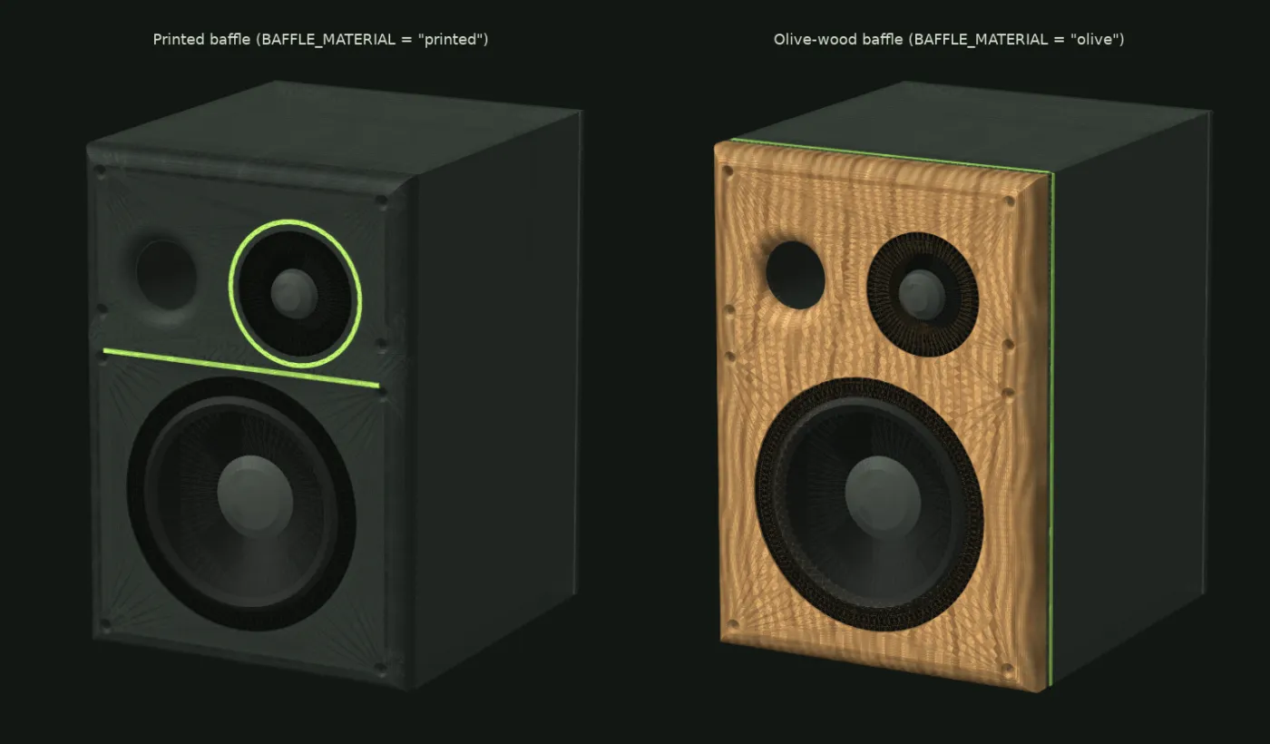
| Printed | Olive | |
|---|---|---|
| Baffle | 2 printed plates, 18 mm, 45° scarf | 1 piece of olive, 20 mm, 210 × 300 mm, R12 roundover |
| Neon accent | Strip on the seam, ring round the tweeter | Green strips in a groove round the printed body, 6 mm behind the wood (sides and top). No groove in the wood |
| Body front | Tongue into the baffle groove | Gasket seat: 5 × 2 mm groove for 5 × 3 mm EPDM closed-cell cord |
| Drivers | Screws into brass inserts | Wood screws in pilot holes (M4 wood inserts for repeated removal) |
| Port | Flare printed in the baffle | R12 roundover routed into the Ø40 bore; a 104 mm printed tube glued in from the back |
| Depth | 236 mm | 238 mm (the extra 2 mm of wood goes forward) |
The first bending mode of the front moves from about 600–700 Hz (printed sandwich) to roughly 0.9–1.3 kHz in 20 mm olive, and the twice-as-heavy baffle radiates less. The printed sides, top and divider keep their 370–550 Hz modes, so the cabinet as a whole still needs the lining and bracing. Estimates from a plate model, not measurements.
Kiln-dried olive blanks, often glued from staves (about EUR 40–100), CNC or carpentry work with the supplied DXF (about EUR 40–100) and hard-wax oil (about EUR 15), minus about EUR 16 of filament. Unverified estimates: get two or three local quotes.
About 79 h and 3.8 kg of filament for the pair instead of 98 h and 4.6 kg (slicer estimates), because the baffles come out of the printer. Each speaker gets about 0.4 kg heavier: each baffle is about 0.78 kg of wood.
A CNC shop works straight from the DXF or STEP. With a hand router, stick the 1:1 template on the front, centre-punch every cross and cut the rebates and cut-outs with a circle jig. Test the rebate depths on scrap so the driver flanges sit flush. Print the body halves, rear plates, port and green strips from the repository’s speakers/stl/olive folder: those body halves have the gasket seat and the accent groove.
04 / Assemble it
Nothing has been built yet, so treat the steps as a plan that the first prototype will correct. Do every step twice, once per speaker. The 3D model below walks through the same eleven steps on the real CAD parts; switch it to the olive front, explode it, or cut it open to see the port, the damping and the board bay.
Loading the 3D model…
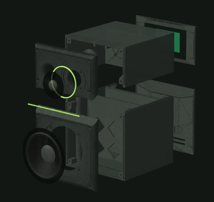
3D isn’t available in this browser, so here are the CAD renders. The steps are listed below.
Drag to orbit. Click the model, then scroll to zoom. Arrow keys orbit, + and − zoom, Home resets.Two fingers rotate and zoom; one finger scrolls the page.
Finished speaker
Left speaker, front three-quarter view. Drag to orbit, or pick a step to watch it go together.
The cabinet is the real CAD. Drivers, amp board, inserts, wiring and damping are simple stand-ins drawn from datasheet sizes.
Use a soldering iron with an insert tip, about 220 °C for PLA and 240 °C for PETG. No solder is involved.
Baffle lower: 4 × M4. Baffle upper: 4 × M3. Body lower: 4 × M4 in the front corbels, 4 × M4 in the column tops at the split, 8 × M3 in the rear face. Body upper: 4 × M4 in the front corbels, 6 × M3 in the rear face, 4 × M2.5 in the board standoffs.
No iron at all? The CAD has a self-tapping option for thread-forming plastic screws, fine for a few reassemblies.
Check the woofer and tweeter sit flush in their rebates, the port tube fits its socket snugly, and the tongue of one body half slides into the groove of the other with light pressure.
Run a bead of sealant in the groove of the upper body, stack it on the lower body and fit the four M4 × 20 bolts: two at the front inside the chamber, reached through the open front, and two in the rear bay. Wipe off squeeze-out inside.
Epoxy (or CA glue for PLA) the port tube into the socket on the back of the upper baffle, flare towards the inside. Check it is square.
Dry-fit both baffles. Then add sealant in the baffle grooves, glue the 45° scarf faces together with epoxy, and fix each plate with four countersunk M4 × 16 screws. Let it cure.
Glue the green strip into the seam groove and the ring around the tweeter, a drop of CA glue every 2 cm. The strip covers the scarf seam.
Line the divider (both sides), the top and the bottom of the chamber with 15–20 mm wadding, about 0.18 m² per speaker, using spray adhesive or hot glue. Keep 30 mm clear in front of the port’s inner end, and add a light loose layer behind the woofer.
Pass two pairs of 0.75 mm² wire, one for the woofer and one for the tweeter, about 40 cm each, through the Ø10 hole in the upper divider. Fit the grommet and seal around the wires with silicone. The box must be airtight. Mark the plus wires.
Crimp insulated female fastons on the wire ends. Measure the tab widths first. If a tab will not take a faston, use a WAGO 221 lever connector on a short tail. Push them on with red (+) to the marked wire.
Mount the woofer with four M4 × 12 screws and the tweeter with four M3 × 10, tightening in a cross pattern only until the flange seats. Over-tightening cracks PLA.
The board lives in the rear bay, outside the sealed chamber. Screw it onto the four standoffs with M2.5 × 6 screws, components facing out through the window. Crimp fork spades on the wires and connect the woofer to output A and the tweeter to output B. Check the silkscreen for which terminal is which. Leave the bay vents uncovered.
Fit the lower rear plate (slots at the bottom) and the upper rear plate (the window) with M3 × 8 countersunk screws, and stick four rubber feet underneath. Plug the 24 V brick’s lead into the board’s barrel jack through the window. The brick connects to the wall with a normal C13 mains cord and stays outside the speaker.
Simplified wiring. Confirm the terminal labelling on your board’s silkscreen.
With the drivers in and the rear plates off, cover the port mouth with tape. Push the woofer cone in gently with flat fingers: it should spring back slowly. A quick return or a hiss means a leak, so check the body split, the scarf, the baffle edges and the grommet, and fix it with sealant. Remove the tape afterwards.
05 / Set up the sound
Use the browser installer for the airplay-esp32 project in Chrome or Edge, pick the louder-esp32-s3-plus target, connect the board by USB-C and flash. The web interface files are included in the web install.
Join your network through the board’s setup access point, then name one “Yolk L” and the other “Yolk R” on their web pages.
In the board’s web interface, mute output B (the tweeter) and set the maximum volume to about 50 %. The factory signal chain sends full-range audio to both outputs, and bass would damage the tweeter until the crossover is in.
Open the board’s /bq equaliser page at its IP address. Set routing to “one channel to both outputs”: Left on Yolk L and Right on Yolk R, outputs not ganged. Use “Build crossover” with “both bands on one amplifier”, 2000 Hz, Linkwitz-Riley 24 dB/oct, then add the three extra filters from the table below by hand. Apply, then unmute B at low volume, listen, and “Commit to flash” once it sounds right.
Temporarily tick Inv on B. The sum should get clearly worse, with a deep dip around 2 kHz. If it gets better, a driver is wired backwards: fix the wiring, not the tick box.
Group “Yolk L” and “Yolk R” in your AirPlay controller (for example Control Center or a Music Assistant group). Play a mono click track and sit at the listening position: you should hear one sharp, centred click, not two.
Levels: A (woofer) 0 dB, B (tweeter) −4.5 dB. Inv: none. These are a simulated starting point and should be refined by measurement.
| Output | BQ | Type | f (Hz) | Q | Gain (dB) | Note |
|---|---|---|---|---|---|---|
| A (woofer) | 1 | High pass, Butterworth 2 | 40 | 0.707 | – | Subsonic guard. Becomes 80 Hz once you add a sub |
| A (woofer) | 2 | Low pass, Butterworth 2 | 2000 | 0.707 | – | LR4 with BQ 3 |
| A (woofer) | 3 | Low pass, Butterworth 2 | 2000 | 0.707 | – | |
| A (woofer) | 4 | High shelf | 260 | 0.6 | −4.0 | Baffle-step compensation, done as a cut to keep headroom |
| B (tweeter) | 1 | High pass, Butterworth 2 | 2000 | 0.707 | – | LR4 with BQ 2 |
| B (tweeter) | 2 | High pass, Butterworth 2 | 2000 | 0.707 | – | |
| B (tweeter) | 3 | Phase shift (all-pass, 2nd order) | 2600 | 0.92 | – | Time alignment: the woofer’s acoustic centre is about 58 µs late and the web UI has no delay block |
The board’s equaliser also accepts raw biquad coefficients; the repository’s DSP file lists them at 48 kHz.
06 / How it sounds on paper
07 / Known risks
A design that has never been built has open questions. These are the ones to know about before you spend 100 hours of printer time.
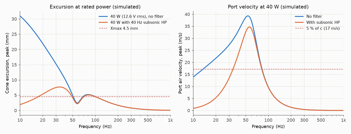
At the 40 W rating the simulated air speed in the port peaks near 35 m/s with the subsonic filter (39 m/s without), well above the roughly 17 m/s where chuffing noise tends to start. Expect audible port noise at high volume. The mitigations are the flared port ends, a sensible max volume setting, and later a sub with the 80 Hz high-pass.
The panels of a printed box ring. The simulation puts the first panel modes of the PLA sides, divider and bottom between roughly 370 and 550 Hz (with 25 % gyroid infill). That is in the vocal range. Lining and bracing help. If the knuckle test still rings, try sand-filled walls or a constrained-layer pad on the sides.
The board is estimated to run about 40 K above room temperature, around 65 °C in a 25 °C room. PLA softens at about 57 °C and PETG at about 69 °C. So the board sits in a vented bay outside the sealed box, the upper body that holds the standoffs is PETG, and you check temperatures after an hour of loud playback. None of this is measured.
Each speaker is its own network receiver. Their multiroom sync is claimed by the firmware authors, but no inter-channel timing figure is published. A skew above roughly 50–100 µs would smear the stereo image. Check it with a mono click track at the listening seat. If it is a problem, a single two-channel board is the fallback.
Every acoustic figure comes from datasheet values and curves digitised by eye (about ±1.5 dB), including the drivers’ acoustic centres, the all-pass and the baffle-step amount. Measure with a USB mic and REW, then refit the levels, all-pass and shelf.
Only AirPlay firmware gives you both streaming and an editable crossover on this board today. Squeezelite and Snapclient are experimental on the S3, and the AirPlay firmware is licensed for non-commercial use only. The Plus board has been sold out on one shop, so check the others.
08 / Next
The speakers are sub-ready: change the woofer’s 40 Hz high-pass to 80 Hz and add a third board in bridged mode with an 80 Hz Linkwitz-Riley low-pass, in the same group. Or use any active sub with an 80 Hz low-pass.
The bigger idea is an all-in-one Yolk Speaker with the streamer, amplifier and power supply inside. This pair is a step towards it: the electronics, the 24 V supply and the DSP tuning carry over, and a custom board could later be assembled by JLC.
The CAD, simulation scripts and sourcing notes are in the Yolk repository’s esp32-hifi-dac/speakers folder, with the full build guide and design notes.